There are a myriad of communications players (technologies) that can be deployed across the smart grid applications layers. The "best fit" technology for any one layer or overall system. The first thing to drive the communications technology decision is the objective for the system. Add in the risk profile of the company and the communications requirements start to take shape.
Smart Grid Communications: Layers and Players
Colin Lippincott | FreeWave Technologies
Much has been written about the Smart Grid including a myriad of definitions and points of view. This paper is intended to provide yet another point of view though focused solely on the application layers, how they impact the Distribution Layer and support the communications technologies at each layer. I intend only to provide my originally formulated thoughts on the various subjects as have been developed from my tenure in the Electric Power and Communications industry. I do pay close attention to discussions with people that I come across who are much more experienced in one or the other or both. I appreciate the contributions from people who have assisted in my career development and my father, who retired as a lineman. The entire smart grid success will depend on communications as a “backbone”. Reliable communications plays a major role insuring that the power generated is distributed properly. Communications has and will always allocate proper distribution of power needed. Research has shown the loss of Power Generated, in the US during generation, could be as high as 20%. A question to ask yourself is; “How would your business survive if it had a 20% inventory shrinkage rate?”
The Power Providing Layer:
The graphic below provides a very high level point of view of the Layers in the grid. Let’s take a few minutes to describe the graphic because the language used from here on out will be referring back to this first graphic.
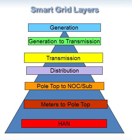
There are three pyramids in the communications graphic below. The pyramid is comprised with layers for the power systems. Though the smart grid is intended to be a cycle of demand, communication and generation or vice versa, for the sake of simplicity this is a hierarchical -top down description.
Starting top of this pyramid is; power generation (there is no power grid to manage if we cannot generate the power).
Generation systems are evolving with the growing advent of distributed power generation from residential systems and commercial power generation systems. As these systems expand, the graphic may need to become more three dimensional. After generation, there has to be power transmission. The power must be delivered close to the consumption point. With traditional and centrally generating power plants it could cause extreme latency. It could also be a very short trip from the rooftop solar PV on the top of my garage right into my meter and house and to the dishwasher.
Power is transmitted from a power source to a system where it is distributed to a consumption point. At this Layer that I call the Distribution Layer there are many types of devices connected to the main system. There are substations “inside the fence” systems, cap banks, reclosers and sensors.
Inside the Smart Grid, this generation especially, the Distribution Layer is a substantially large percentage of the Smart Grid. As a standalone system, though, the primary objective for the system is fundamentally the same as it always has been. That objective is to reliably, affordably deliver enough power to the consumption side of the Smart Grid satisfying demand.
Distribution Automation has added a new objective or at least a new dimension to the original objective. This objective is to provide communications to all of these devices so that up time is maximized as long as that maximization is achieved affordably. It has been proven that the right system tools will help the utility satisfy customers, shareholders, members or taxpayers. The improvements in system uptime are dramatic if not invisible to the consumption side. People (or companies) don’t notice when power is being successfully provided. They do notice immediately when power is not being provided whether for a short or long interval.
Shareholders, members or taxpayers in IOUs, co-ops and municipalities enjoy the benefits of distribution automation, too. If there is an outage for any length of time, the utility can intelligently decide how to disseminate the real time information for improved decision making. Decisions would be make such as; do we roll trucks or can we perform restoration from the office? Did the recloser manage the outage automatically?
If, like me, you have worked for the utility or grew up in a utility household (I did both), you are probably familiar with the methods used to identify outages in the past. The utility that I worked in as a ground man (yes, a grunt) or sometimes equipment operator is a rural electric co-op. When the co-op would first learn of an outage we would jump in the trucks (me with the linemen). Out on the road we would deploy the look up method to find the specific cause of an outage. Yep, we would drive the line and look up! That method has become more and more expensive in hard dollars and very inefficient in soft dollars and customer PR.
The Consumption Layers
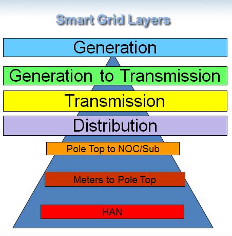
The residential and the commercial side of the consumption layer are basically the same. Reviewing the graphic below, I have separated the HAN system from Demand Response only because, for my purpose, they differ in size and scale.
.jpg)
The HAN system is uniquely intended as its name defines the “home.” I am using the demand response system for the commercial and industrial side. Both systems are intended to give the system controller (mom or the plant manager) the tools to manage power consumption. Each entity can closely optimize the power consumption by allowing information required to intelligently decide its duty during the consumption periods, whether peak or off-peak times. With variable rate systems being deployed, the system controller can do more than optimize consumption for the greater good, they can also substantially increase savings for a business or home.
These systems (demand) are captured by the HAN then communicated back “upstream” to the power provider. The data can be wirelessly disseminated up to a collection point where several or many meters’ data are aggregated for communication to a gateway link to the decision system. The gateway layer and the collector layer device might be the same in any system or could be separate devices. For example: one large IOUs AMI system, the meters communicate to the collector and the collector to a gateway device installed on a backhaul tower. Albeit, another system could have the collector AS the gateway and can serve as the backhaul, too. How that is articulated is up to the system architect in the design.
As we did with the power providing side, let’s take a look at the historical objectives of this side of the business. The original metering systems were put in for one primary reason – billing. Those systems provided data to the human meter reader who peered into the glass to read the scrolling numbers. After decades of that original system the AMR systems began to be installed and evolve. These systems also had billing as the primary objective. Most systems had one way communications from the meter to a collector whether that collector was on a pole top, in a driving-by vehicle or a walking by human carrying a receiver.
AMI and the Smart Grid have come along and the objectives have expanded. Certainly, billing remains as an important objective. Other objectives are articulated in support of the power providing side. The data from the meter and inside the building are used by the utilities’ intelligent decision support systems to direct power to where it is needed and away from where it is not needed.
Communications Players:
The objectives and the high level descriptions of the layers are relatively simply to discuss especially at a simplistic, high level view as used in this paper. Discussing the communications players can have many more complexities. The place for any utility to decide on what player type to select for any layer is first dependent on one thing: system objectives. Once the system objectives are clearly articulated, the selection process amongst the player’s options can begin in earnest. This is not to argue necessarily that the objectives themselves will clearly point to any single communications option but provide important guidance on how to make the choices intelligently.
Let’s go back to the graphics. Here is graphic three emphasizing the power providing side of the grid. Let’s take a look.
My first caveat with respect to this graphic is that I have used “etc.” because I know that someone can come up with one or more additional technology players to be considered for use in any layer. My goal is not necessarily to create the exhaustive academic paper covering all known technologies in each application. Rather, my goal is to provide information on systems that are being deployed in great quantities AND that I have some experience with either directly or tangentially through our customers and industry friends.
Plus, I am focusing the rest of this part of the discussion on the distribution layer and where that layer interconnects with the consumption side – the gateway. This is where the volume of communication equipment is being deployed in the smart grid (not including the meter layer, of course).
Unlicensed Radio Systems:
Wireless technologies of many types with many different capabilities from many different suppliers are deployed at these layers and the overlap is significant. Unlicensed radio systems are often used because of advantages ranging from the fact that they do not require licenses to the bandwidth potential. These systems are proven to be reliable and secure. There are three network topologies that I want to share with you with these systems. They can be deployed as point-to-multipoint systems as shown in figure 1, in mesh systems as shown in figure 2 or point-to-point systems as shown in figure 3. Point-to-point systems are best suited as backhaul systems and are not further discussed in this paper.
.jpg)
Figure 1: Point-to-Multipoint
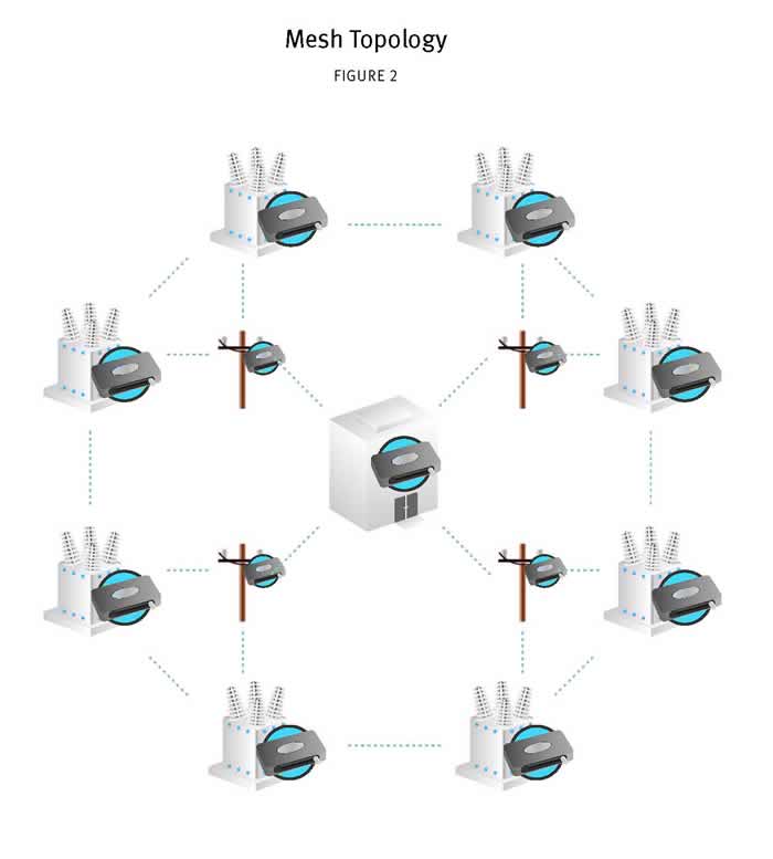
Figure 2: Mesh
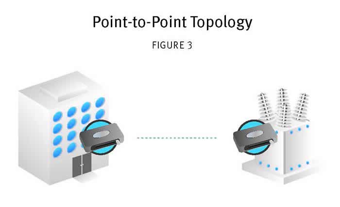
Figure 3: Point-to-Point
Point-to-Multipoint (P2MP) systems have some advantages in particular, they can be deployed either with or without repeaters in the network. A system without repeaters will have about double the overall system throughput than one with repeaters. All things being kept equal, the P2MP systems also can have greater overall system throughput than Mesh systems. Not all radios are “created equal” so there are exceptions to this rule so think more of it as a heuristic than a rule.
Figure 4 shows the P2MP example with repeaters deployed. These systems are sometimes, fairly, evaluated as having failure points that make it difficult to “see” points on the other side of the repeater. Though are rare occurrence in top quality radios, there can be a comms failure at any point in the system even the repeater. Of course, the way to assure that there are no repeater location points of failure one can design the network such that there are no repeaters. That design assures that the master radio can see and communicate with every remote radio in the system. If a remote radio does stop communicating for any reason, a top quality radio system diagnostics GUI will pinpoint that radio. With that information, the operator can make intelligent decisions on what to do about the comms loss.
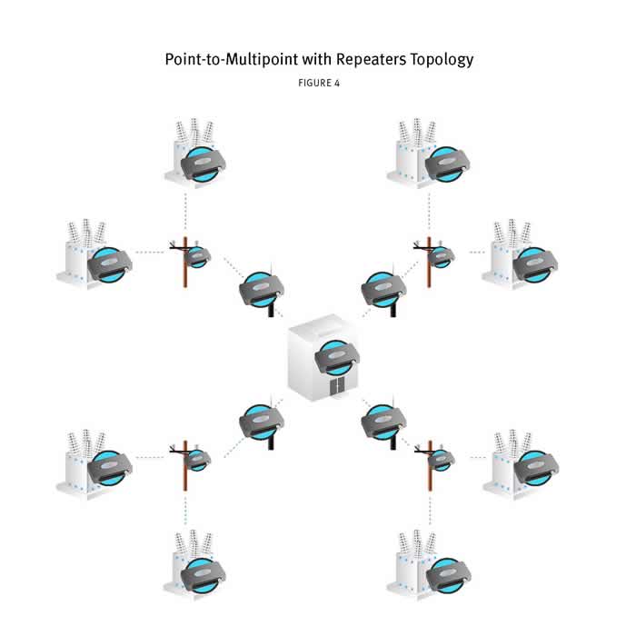
Figure 4: Point-to-Multipoint with Repeaters
The mesh systems do offer the advantage that they overcome the repeater comms loss by having every radio provided with more than one path back to the master. That is typically accomplished with significant infrastructure to assure that the design supports multiple path options back to the master. Even this design does not completely remove the possibility of a radio or several can be isolated and not communicating with the master. The bottom line for all communications systems whether wired or wireless is that there is risk associated with successfully getting data from point A to point B and back. Each technology manages that risk in a way differently from the others.
Licensed Radio Systems;
There is one such technology that makes assumptions and sacrifices to achieve robust communications. That is the licensed radio system. Licensed radios work with the assumption that the spectrum licensee will not be interfered with by other devices because the FCC (or spectrum owner) will not allow any other user on that frequency. That is a successful endeavor most of the time.
What keeps everyone from using licensed radio systems? Licenses are sometimes difficult to obtain in various frequencies because the FCC has previously licensed it to other users. Other frequencies might be prohibitively expensive for some companies even if licenses are available.
If the system objective includes getting high bandwidth and high volumes of data to the host, licensed radios are often challenged. In the 400 MHz spectrum, for example: it can be quite difficult to obtain a license that provides wide enough channel spacing to get the data volume required while attempting to meet the applications objectives. The 200 MHz systems for example: It can achieve much higher throughput if sufficient spectrum is acquired. Pricing for this spectrum varies based on too many inputs including the spectrum owner’s objectives, location, population and more.
An advantage that both unlicensed or licensed radio systems have is coverage. Radio systems have coverage where ever they are properly installed. Certainly, as things change in the coverage area, coverage can be compromised. A system redesign can usually recover the full coverage expectations and required throughput.
Cellular Systems:
Cell phone based systems have a great advantage over radio systems whether unlicensed or licensed. It is simplicity in deployment. The engineering required with radio systems in a network design is simply not required for cell phones. If coverage exists, one will initiate, hook ‘em up, turn ‘em on and get data.
There are tradeoffs with cell phone based systems which is why some utilities chose radios over them. These systems do come with monthly charges with varying data plans they are public systems that share spectrum with any other device with the provider. As any of us who use a cell phone know, there are some risks associated with the robust nature of a system. If there is a system outage that is only resolved when the carrier gets the system in recovery. In the simplest terms; the radio system owner can immediately address the status of the system or any single locations. Cell systems don’t offer that advantage.
If the area is a high density, high coverage topology, using public spectrum and cell phone systems are a great choice for all applications in the systems. In Rural areas, the coverage could be sparse.
PLC and Fiber Systems:
PLC and Fiber wired systems are different than wireless systems in the aforementioned. Fiber optic cable has the single best reliability over all other systems with the greatest cost. Nothing beats fiber for where it can be affordably deployed. Fiber systems do fail from various causes as every system has its risks.
PLC systems are gaining popularity as the technology improves. In power line communications systems, data is simply transmitted along the existing power lines.
Hybrid Systems:
Because no technology or system is isolated from dysfunction, risk management often requires that systems such as distribution automation, reside on a system separated from AMI. System objectives and priorities can differ from organizations, and departments, the option of deploying a hybrid system is a more viable option.
An example of a Hybrid system is if a large IOU deploys a fully functional smart grid system with communications covering all applications in this example, especially the DA and AMI applications. AMI systems have many points and a lot of infrastructure as a natural requirement of the system objectives. For those reasons alone, the meshing radio systems provide a great tool for the application. There is enough system density in deploying mesh radios it can reliably detect another radio or enough radios to prevent an isolated system and loss.
In another scenario, the DA system has its own objectives no matter the state of the AMI system, it must deliver power to the customers. The AMI system provides critical information for providing data the best way and the most efficient manner. The DA system, however, can deliver power to the customers, the consumption side, even in the event that the AMI system is not providing data. The DA system can and must simultaneously provide system status (outage or no outage) no matter the state of the AMI comms system and vice versa. Because the level of criticality differs between AMI and DA, the systems should be on different networks.
Conclusions:
There are a myriad of communications players (technologies) that can be deployed across the smart grid applications layers. The “best fit” technology for any one layer or overall system. The first thing to drive the communications technology decision is the objective for the system. Add in the risk profile of the company and the communications requirements start to take shape.
Is the driver for the system reliability with no consideration to cost? Then, fiber optic cable has got to be the choice. Of course, I can’t think of any utility that has such resources. And, certainly practicality becomes a variable in the selection of wireless over fiber. How many highway departments are going to flippantly allow trenching and associated delays with costs to the department and its constituency? None, to my knowledge.
After considering the advantages of the technologies themselves, it is also important to consider advantages and disadvantages of any supplier. The top tier providers will sort themselves out quickly when it comes to reliability, security, service and long term viability. They also have to have a cultural fit with the utility culture. If there is a clash in cultural expectations the implementation and post implementation relationship can offer challenges that can be overlooked in the selection process.
Lastly, the hybrid system might be the best technology choice. Separating the applications from one another by communications systems just makes sense. Putting the entire system’s eggs all in one technology basket is risky especially in the event that the utility does not actually even control the basket. There are situations where the utility is exploring using the public WiFi system for critical infrastructure. The cost advantages are definitely in place. Are the risks too much? Only the network owner can make that decision.
Best of luck to all the system owners out there. These are promising times with great potential for the smart grid to make improvements that positively affect all of our lives from rate improvements to national security.
The content & opinions in this article are the author’s and do not necessarily represent the views of AltEnergyMag
Comments (0)
This post does not have any comments. Be the first to leave a comment below.
Featured Product
MORNINGSTAR - GenStar MPPT
GenStar MPPT is the industry's first fully integrated solar DC charging system, an all-new design with "lithium DNA" from the leader in charge controllers. Out of the box, GenStar is an overachiever-delivering legendary Morningstar quality, efficiency, power and reliability along with the latest in advanced communications and control technologies. All the most installer-requested features are on-board; additional features can be easily added via Morningstar's ReadyBlock expansion technology, with snap-in blocks that provide battery metering and monitoring, signaling and load control, and lithium battery communications/control