I live in the middle of the woods out in the country in Ohio; far enough out where there is no cable service, no gas, no piped-in water, no sewers, cell phones don't work, the grid provides reasonable power most of the time, and the one analog-POTs telephone line works if there is not too much water in the crick.
A Daunting Expedition Through The Energy Harvesting Countryside - Part 1
Thomas W. Gustin
ENERGY HARVESTING; WHY TRY:
I just wanted to reduce my carbon footprint and help everyone in the process. OK, maybe that is too lofty of a goal; yet, the desire remains with the will to try. Being a creative hardware engineer since 1976 has long taught me that running down to my local Radio Shack store was not going to provide an integrated solution. Starting out at zero on the learning curve, this project’s scope grew exponentially with every piece of data I digested. Put another way, the more I learned about energy harvesting systems the more I realized how little I knew.
I live in the middle of the woods out in the country in Ohio; far enough out where there is no cable service, no gas, no piped-in water, no sewers, cell phones don’t work, the grid provides reasonable power most of the time, and the one analog-POTs telephone line works if there is not too much water in the crick. We call our place The Emerald Cave, out of sight and very green when the leaves are on, with a full canopy. The trees are so thick that no satellite services are available without cutting down a wide swath of trees (there is nothing of value from a satellite to warrant cutting down a single tree, let alone hundreds of them). Harvesting sunlight is going to be difficult when the leaves are all on.
I am not complaining; these are all great advantages to living a balanced life, mostly disconnected from the e-distractions afflicting most of our friends and families. It takes a long time to download a tiny file, providing an opportunity to put more wood in the fire and fill my coffee cup, and maybe start another load of wash. When the power goes down (typically four hours to four days at a time), as it does a dozen times per year, I use my emergency back-up generator with self-designed and wired off-grid power-circuits for the essential services (while also burning gasoline and making a lot of noise :-(. I want to run this generator even less, maybe not at all eventually, if possible.
CONSERVATION:
The overall task of using less grid-based power succeeds by swinging the dual-edge sword of conserving and harvesting of energy. As with very large engineering projects, success often comes by taking many much smaller, manageable steps, rather than trying to accomplish the whole project in just one gigantic try. A few examples of easy-to-implement conservation steps follow.

Living in a biomass wonderland, we burn dead (from natural causes) wood for heating about 6 months of the year. A few years ago, after burning multiple large holes through two layers of ¼” boiler plate firewalls in our 30% efficient wood burning insert (Shagbark Hickory really burns hot), we invested in an 87% efficient “modern” wood burning insert (Figure 1) that virtually terminated chimney smoke and its suspended particulates (reducing pollution), burning less wood with better heating efficiency. The icing on the cake is all the great exercise I get logging, hauling, splitting, stacking in the woods for seasoning, and then restacking in the barn for eventual burning all of this (almost) free fuel, augmenting the dead trees’ usefulness by converting all of it to heat and very little ash (spread onto soil as a natural sweetener). This fireplace has already paid for itself (took 2½ years) in money saved by not using our electric baseboard heaters. Measuring its dual-blowers power requirements with a “Kill A WattTM” meter, the fans require 39watts (at minimum speed) to 69watts (at high speed). Sounds like these blowers might be a good candidate for environmentally scavenged power.
Figure 1: High Efficiency Fireplace Insert with low power blowers
Ohio Winters can be depressingly gloomy, with nearly constant cloud cover. Even with the leaves off the trees, photovoltaic (PV, solar) panels will not be contributing their maximum rated power most of the time. Additionally, last year I replaced our single 500Watts Halogen Floor Lamp fixture with six PAR30 long neck LED lamps in (old-style tabletop gooseneck) bullet fixtures in our living room (opposite the fireplace), up high and behind our reading chairs. I used four bulbs rated at 3500K (Bright White) and two bulbs rated at 2700K (Warm White) to circumvent successfully previous years’ “mood” issues with winter weather. The total light output in the living room is noticeably (albeit, unscientifically reported) much brighter with these six LED lamps than with the single 500Watts Halogen Lamp. …drum-roll please… Measuring the power requirements with the “Kill A WattTM” meter, all six LED lamps require 14.1Watts total.

Figure 2: Energy Conservation: LED Lamp Fixtures
A small humidifier sits on the brick hearth, running non-stop during the winter heating months, (just right of the piece of wood in Figure 1) maintaining comfortable, non-static-zapping humidity levels. Measuring the power requirements with the “Kill A WattTM” meter, the humidifier, with its anti-bacteria ultra-violet light activated, only requires 14watts (at its low fan speed) up to 40watts (at high speed).
More conservation steps, like these, will occur as the move towards putting various loads, like these, on scavenged power, as possible. For those keeping tally, the power needed for wintertime emergency backup energy for lights and heat is now at 123.1Watts maximum. Of course, much more power is required for running a stovetop burner or two, or a 1kW Microwave oven, the deep-well water pump when needed, maybe even the electric hot water heater, etc.
ALL OR NOTHING:
Retailers and Installers of many existing Solar or Wind Energy Harvesting Systems typically propose buying and installing enough capacity to run all of the loads available, selling excess capacity back to the utility companies via their (very expensive) grid-tie inverter and special (can actually spin backwards) grid-power meter. This is not a do-it-yourself project, nor is it cheap. Research into all of the permits, regulations, licensing, insurance, hardware, and labor costs is a real eye-opening experience, and it exposes much of why so few residential energy harvesting systems are installed.
Further research into the hardware required to build a system reveals another anomaly regarding system architecture. There is the “solar” camp; and, there is the “wind” camp; and the two shall not work together, unless forced to do so. Well, I have wind sometimes, and I have some light sometimes; and, I want to gather energy from both when possible, using a Hybrid Energy System approach.
SYSTEM GOALS:
This first example presents a system built using commercially available pieces to operate at approximately 2kWatts peak, so that it will work for about 2 days providing about 200 Watts of power as an emergency back-up system during our frequent power outages. This capacity will permit short-term high power loads (like a well pump) to be powered briefly, with other smaller loads running continuously. It would also be nice to have (good-luck with this one) a system-wide integrated Health Monitoring System reporting the system status.
WARNING |
|
Certain home improvement projects are inherently dangerous, and even the most benign tool can cause serious injury or death if not used properly. ALWAYS READ AND FOLLOW INSTRUCTION MANUALS AND SAFETY WARNINGS. You must be particularly careful when dealing with electricity – always use common sense. Any advice, guidance or other information provided on the altenergymag.com website or within any of our publications cannot completely anticipate your situation. If you are at all unsure about completing any aspect of this or other home wiring projects, consult a qualified electrical contractor to perform the service(s) for you. ALWAYS follow electrical code requirements specific to your area, and before undertaking any home electrical project, contact your local electrical authority and your insurance company to ensure that you comply with all policies, warranties, regulations and authorities concerning this work. |
2kWatts OFF-GRID Energy Harvesting System Approach #1:
Like money (» energy) in the bank, the heart of this configuration of off-grid energy harvesting system is the battery bank. Various energy-harvesting resources (solar panels and wind turbines in this example) deposit energy as it is available (called “opportunity charging”); the loads withdraw energy from the battery bank as long as there is sufficient energy available.
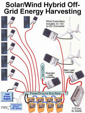
Figure 3: Hybrid Energy Harvesting System using Commercial Controllers
Key to sustaining long operational life in this kind of system is the proper energy maintenance for the particular kind of batteries chosen. Figure 3 shows an eight-battery bank constructed from 6volts, 390Ah-rated AGM batteries (from US Battery). With two parallel sets of four batteries series wired the nominal operating parameters is 24volts at 780amp-hours capacity. Later I will discuss this particular battery configuration in more detail.
Battery energy maintenance consists of two primary controlling operations:
- NEVER Over-charge the batteries; and,
- NEVER Over-discharge the batteries.
Figure 3 gives you an idea about how eleven different Commercial “controllers,” working independently, accomplish these two prime tasks.
For brevity’s sake, Figure 3 only presents about half of the heavy-gauge wiring. Following common conventions: red wire is for positive and black wire is for negative. Use both cables for all sources and loads.
This Energy Harvesting System, somewhat contrived for this example, depicts one that is able to scavenge »1.4kWatts of power from direct overhead bright sunlight through the six solar panels (not going to happen here at the Emerald Cave). 600watts of power (maximum) comes from the pair of small (300watts each) wind turbines when we get our occasional tornado or hurricane (has happened recently) blowing through; although, many days have no breeze at all. I am building this system to have a 2kWatt capacity so that I can run my 200Watts loads for a couple of days without wind and light, if necessary.
Most Commercial “controllers” are three function controllers that provide solar battery charging, or load control, or diversion load protection. They do NOT perform these three necessary, yet different functions simultaneously. Most wind turbines output 3Ø AC power (instead of DC). A three-leg full wave rectifier on the input of the wind turbines’ dedicated charge controllers changes the AC to DC, as needed. Wind turbines cannot be (safely, electrically) disconnected from the system (due to very high open circuit voltages in high winds) when the battery is fully charged. Instead of disconnecting the wind turbines, the diversion load controller connects a customer supplied resistive load to prevent battery over-charging. The charge controllers connecting the solar panels to the battery bank individually disconnect their respective solar panels when the batteries are at full charge (to prevent dangerous over-charging events).
The 200Watts 115VAC loads in this example obtain their power through the main load controller (which turns off if the battery’s voltage drops too low) via the 24volts DC-to-115VAC Inverter. A second inverter of higher capacity, with surge capabilities, can also easily run high power loads for short durations (like our micro oven, or even our water well pump, etc.).
EMERGENCY BACKUP for the EMERGENCY BACKUP:
“NEVER Over-discharge the batteries.” What happens, while continually drawing 200Watts, when there is no wind and total cloud cover for many days? The reserve energy in the batteries supply (evidenced by the decreasing battery voltage; more on this later) power to the loads until a special circuit (see bottom left of Figure 3) determines that the system “needs more power.” This “over-discharge protection” circuit then turns on a grid-tied 1kWatt power supply that recharges the batteries to their full state to prevent discharge-level premature reduction of cycle-life. These batteries are very expensive; the longer they run at their maximum charge level the longer they will remain in service.
BURNING OFF TOO MUCH HARVESTED ENERGY:
“NEVER Over-charge the batteries.” What happens when there is a lot of wind in bright sunlight, harvesting far more energy than what the continually running 200Watts loads need? The individual solar charge controllers will disconnect their individual solar panels from the battery. What happens if it is still very windy, where both wind turbines are still supplying more energy than what the loads need, and the batteries are completely full? Under these conditions, the Diversion Load Controller (see Figure 3) turns on a “user supplied resistive load” to (quite literally) burn off the excess harvested energy (from the wind turbines), as an extra (do-nothing but get hot) load. There are system-level constraints for this safety load. It must never be light bulbs (that could fail open), motors, or other electrical devices. Most installations use electric hot water heating elements. The big problem with this is finding the correct equivalent wattage rating to function properly. The safety load for our system must be 600Watts at 24volts (maximum power from both wind turbines); while most hot water heating elements run at 115VAC or 220VAC, usually in the multi-kilowatts range.
DETAILS BEFORE IMPROVEMENTS:
Some areas for system improvements exist, some noted above while others will become evident as discussions continue. At this point I wish to move from the top-down view to exploring various system component details from the bottom up, starting with the energy-heart of our system, the batteries.
BATTERY SELECTION:
The first question that comes to mind is how one selects the best voltage for the battery, 12 versus 24 versus 48volts. Generally, the safest system uses the lowest voltages possible, within reasonable limits of current handling capacity (for both the batteries and their large connecting cables), coupled with awareness of the availability of reasonably priced system components (like solar panels, wind turbines, the output load’s inverter, and controllers). Table 1 presents a very rough overview of some of these issues.
The reader will note that for a 2kWatt system, the designer would normally use a 48volts battery system to reduce the cabling size. However, since a low power (250watts) inverter for the normally on, 200watts’ loads, is not obviously available for this particular application, 24volts batteries are being used. With two parallel battery banks, 780amp-hour capacity enables using a second, higher capacity, surge capable inverter to run, for a short time, high power loads in this system (as an emergency backup system for the well water pump).
|
12volts |
24volts |
48volts |
|
<--lowest voltages = safest systems; higher voltages for higher power systems --> |
||
|
<= 500Watts |
< between > |
>= 1kWatts |
|
<--lowest voltages = least expensive systems; higher voltages much more expensive systems --> |
||
|
For 115VAC 250watts Pure Sine Inverters: |
||
|
Many available, inexpensive |
A few available, reasonably priced |
Couldn’t find any available |
Table 1: Battery Voltage Selection Matrix
Picking the battery voltage is the easy part of the task. Picking the right battery capacity is a bit more difficult task; made much easier with easy-to-use Internet tools, like those at www.batterystuff.com.
Ok, I will admit that the batteries selected for this project, the same ones depicted in Figure 3, are ones based upon previous system’s development experience. Therefore, that which follows is a confirmation that the eight L16 AGM batteries in our system will meet our requirements of running as an emergency backup system for at least two days with no energy harvesting occurring.
US Battery Manufacturing Company supplies two rated-capacity values in its data sheet for the (single) L16 AGM (a great lead acid battery for minimum maintenance and maximum cycle-life) batteries:
- 390Ah at a 20 hour rate (19.5amperes for 20 hours); and,
- 331Ah at a 5 hour rate (66.2amperes for 5 hours).
These rates, by the way, assume starting from a 100% State-Of-Charge (SOC) allowing for a complete discharge to 0% SOC. Battery manufacturers also use inverse terminology, where 0% SOC equals 100% Depth-Of-Discharge (DOD) and 100% SOC equals 0% DOD.
NOTE: As the rate of discharge increases, the available capacity of that battery decreases.
BALLPARK BATTERY CAPABILITY CHECK:
Since it is a goal to operate our system nonstop for at least two days without the benefit of energy (harvesting) recuperation at 200watts, the “Calculator to Determine Run Time for Specific Load” (at www.batterystuff.com) is a good tool to use for this assessment. For those who are curious (reads as: for the Nerd inclined), their write up on Peukert’s Law is excellent background information. Using (a parallel pair of batteries) 780AH capacity (20-hour rate) and 662AH capacity (5-hour rate) from the L16 data sheet, Peukert’s constant is 1.234200218. Note that this constant will be less for batteries more than 6 months old, or for batteries exposed to temperatures over 85°F or under 0°.
The value of 200Watts as our load consists of 176Watts of actual 115VAC loading, added to the 24Watts of power used by the Inverter to convert the 24volts DC to 115VAC (at 88% efficiency = typical value). 200Watts loading on the 24volts (nominal) battery draws a current of 8.3amperes. Since the actual amperage of 8.3amps is much less than the 20 hour rate of the battery, its total capacity is actually much higher than the (two parallel battery sets of) 790AH capacity. The “Run Time Calculator” indicates that the (adjusted) capacity of our battery bank is 1120.66AH at a 135.02-hour rating under our 8.3amperes loading.
This means that it will take 5 days and 15 hours to drain completely our battery from 100% SOC to 100% DOD (very bad idea to drain the battery completely). Under normal, non-emergency conditions, it is best only to drain a battery to its <=50% DOD to ensure long cycle-life. Therefore, under constant 200Watts of loading, our new batteries, operating at room temperature starting from a fully charged state with no energy harvesting replenishing energy, will run for 2 days and 19.5hours (best case scenario). Table 2 depicts a few values for the trade-off between emergency run times versus corresponding SOC %’s.
|
% SOC |
Run Time |
Expected Cycle Life |
|
90 |
13.5 hours |
19 years, 2.1 months |
|
80 |
1 day, 3 hours |
9 years, ½ month |
|
70 |
1 day, 16.5 hours |
5 years, 7.4 months |
|
60 |
2 days, 6 hours |
4 years, ½ month |
|
50 |
2 days, 19.5 hours |
3 years, 1.8 months |
|
40 |
3 days, 9 hours |
2 years, 7.2 months |
|
30 |
3 days, 22.5 hours |
2 years, 1.6 months |
|
20 |
4 days, 12 hours |
1 year, 10.2 months |
|
10 |
5 days, 1.5 hours |
1 year, 7.4 months |
|
0 |
5 days, 15 hours |
1 year, 4.4 months |
Table 2: Run Time and Expected Cycle Life per % DOD
Note that the Expected Cycle Life (column) data is “informative” only, since its derivation assumes different operating conditions than those we are using. The Data (from a curve from US Battery Manufacturing Company) assumes one full cycle from 100% SOC to the (row) end %SOC value and back to 100% SOC again, once per 24-hour period, at a 20-hour capacity rate. “Opportunity-charging,” while energy is available from harvesting resources, strives to maintain the SOC as high as possible, thereby lengthening the expected cycle life.
MORE BATTERY CAPACITY INFORMATION:
Using the top half of the “Solar Calculator” (again at the BatteryStuff web site) to play with various (input) operating parameters yields interesting data about the capabilities of this system design.
|
Load Watts |
Hours per Day |
Watt-Hours per day |
Battery Losses Corrected Watt-Hours per day |
Amp-Hours per Day |
Assumed Battery Capacity |
# of 24 hours Days Backup |
|
200 |
24 |
4800 |
4896 |
204 |
613 |
3 |
|
1000 |
1 |
1000 |
1020 |
42.5 |
613 |
3 |
|
250 |
24 |
6000 |
6120 |
255 |
613 |
2.4 |
|
300 |
24 |
7200 |
7344 |
306 |
613 |
2 |
|
300 |
24 |
7200 |
7344 |
306 |
650 |
2.12 |
|
300 |
24 |
7200 |
7344 |
306 |
700 |
2.29 |
|
300 |
24 |
7200 |
7344 |
306 |
730 |
2.39 |
|
300 |
24 |
7200 |
7344 |
306 |
760 |
2.48 |
|
300 |
24 |
7200 |
7344 |
306 |
780 |
2.55 |
Table 3: Days of Backup for various Loads and Battery Capacities
The astute reader may notice that this tabulation is ultra-conservative because it includes two different degradations for battery capacity:
- Battery Losses Correction (fourth column) is a slight “static average loss” within the Solar Calculator; and,
- Assumed Battery Capacity (sixth column) represents some significant losses (the lower values in the first six rows) attributable to various causes, including old age, repeated insufficient recharging back to 100% SOC, and extreme temperature conditions (similar to people-old-age syndrome :-).
The first four rows vary the load wattage for results, noting that the second row also changes the running time to just 1 hour per day (this represents our high power loads of water well pump and microwave oven). The remaining rows vary just the battery capacity to establish its significant effect on the total number of days of emergency backup power available. The 300watts of load power for these latter rows is an approximate average of our low power loads (lights, heater blower, humidifier, small circulation fans, etc.) running 24 hours a day with occasional high power loads (refilling the water bladder tanks, “zapping” a meal, etc.).
INVERTERS:
Figure 3 only shows one inverter attached to the main load controller. Using our dual load model of constant (200watts) low power load and occasional (1kW) high power load, there will actually be two inverters attached to the main load controller(s). Whenever an inverter has an inductive load, like a motor (water well pump) it should also be capable of high startup surges. I also recommend using “pure sine” instead of the cheaper “modified square” (quality of AC output wave) inverters, because the latter is less efficient for many kinds of loads, and can actually damage some older sensitive electronic devices. There are many sources of good quality inverters, being a mature technology. The key research parameters include the nominal input voltage (24volts for our example), continuous and surge power ratings for a given output voltage, and a preference for sinusoidal, versus modified-square, waveform on the AC output.
Just for the sake of this example (not implying endorsement or ranking over competitors), a couple of models from Exeltech in the XP Series are shown for their applicability.
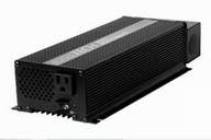
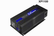
Figure 4: Exeltech's XP250 (117Vac) & XP1100 (230Vac) Inverters
Figure 4 depicts two different Exeltech inverters that will work for our particular example application. The XP1100 (far right) provides 1100watts continuous power capacity with the ability to handle surges to 2200watts (for starting our well water pump). The XP250 provides 250watts continuous and 300Watts surge power capabilities.
These inverters run with a wide input voltage range of 19volts (minimum) to 33volts (maximum), with a low voltage warning buzzer sounding when the battery voltage drops to 21volts. The 250Watts unit uses convection cooling, is 2.77” x 5.23” x 12.03” in size, weighing just 5 pounds. The 1100Watts unit uses thermostatically controlled forced air-cooling, is 3.57” x 7.69” x 15.05” in size, weighing 10 pounds.
Properly designed over-charge protection and over-discharged protection circuitry, handled by settings on all of our commercial controllers in this example, will prevent the battery voltages from approaching either the minimum or maximum voltage parameters for these inverters.
SYSTEM STATES and the BATTERY STATE OF CHARGE:
|
Volts per Cell |
per Battery Voltage |
Total Battery Voltage |
~ State of Charge[1] |
System Functions |
General System Notes: |
|
2.740 |
8.220 |
32.88 |
Battery “topped off” |
Resistive Diversion Load Connections and Solar Panel Disconnections as needed |
Low Temperature Maximum Charging Voltage level at -40°C |
|
2.583 |
7.749 |
31.00 |
9-controllers Over-Charge Protection prevent damage to the batteries |
||
|
2.450 |
7.350 |
29.40 |
|||
|
2.300 |
6.900 |
27.60 |
High Temperature Maximum Charging Voltage level at +50°C |
||
|
2.250 |
6.750 |
27.00 |
Optimum "Float" Maintenance, post-recharge, voltage level |
||
|
2.120 |
6.360 |
25.44 |
100% |
"Opportunity Charging" Region with Main Loads Attached |
Optimum Working Region of Battery-based Power System, favoring (of course) the higher voltages if energy from the Resource Generators (including Solar Panels and wind turbines) permits |
|
2.083 |
6.249 |
25.00 |
90% |
||
|
2.046 |
6.138 |
24.55 |
80% |
||
|
2.009 |
6.027 |
24.11 |
70% |
||
|
1.972 |
5.916 |
23.66 |
60% |
||
|
Volts per Cell |
per Battery Voltage |
Total Battery Voltage |
» State of Charge1 |
System Functions |
General System Notes: |
|
1.935 |
5.805 |
23.22 |
50% |
Turn on 1kW Power Supply |
Alert sent (& SSR closure) of "NEED MORE POWER" state. Adjustable Threshold |
|
1.898 |
5.694 |
22.78 |
40% |
Life Cycle Preservation Mode: NO LOADS |
Over-discharge Protection Circuits: Main Load Controller disconnects the main loads to preserve the battery’s cycle life. Adjustable Threshold |
|
1.861 |
5.583 |
22.33 |
30% |
||
|
1.824 |
5.472 |
21.89 |
20% |
||
|
1.787 |
5.361 |
21.44 |
10% |
||
|
1.750 |
5.250 |
21.00 |
0% |
||
|
"Opportunity Charging" is defined as recharging whenever there is significant discharge and there is a convenient opportunity for recharging." “ … (it) not only maximizes available run-time, but also maintains the battery in a healthy, fully charged state."[2] |
|||||
Table 4: Battery State Of Charge with System States Tabulation
So far, we have examined the energy bank, and the loads upon it. Next, we will explore some of the energy harvesting needs and capabilities.
Continued in Part 2
1 Linear derivation, where 1.75v/cell = 0% & 2.12v/cell = 100%; \ SOC% » [270.27 X Cell Volts]-472.93. Normally SOC% is (an open-circuit) estimation. These values are used in this system fully loaded; hence “approximation only.”
2 "Charging Characteristics: Flooded Lead Acid and Sealed Lead Acid Deep Cycle Batteries" by K. Fred Wehmeyer, Vice President, Product & Process Engineering at U.S. Battery Manufacturing Company, Inc.
The content & opinions in this article are the author’s and do not necessarily represent the views of AltEnergyMag
Comments (0)
This post does not have any comments. Be the first to leave a comment below.
Featured Product