The regulatory requirement to prove collision-friendly foundation design need not be a cost-intensive mandatory additional measure, but may be an opportunity that significantly improves reliability and safety. It would increase the lifespan of the primary structure of the wind turbine, preventing subsequent time- and cost-intensive repairs.
Bj�rn Kramer | T�V S�D Industrie Service
As wind turbine sites increasingly move offshore, new challenges arise in the calculation and evaluation of collision impacts. For official approval to be issued, the German Maritime and Hydrographic Agency (Bundesamt für Seeschifffahrt und Hydrographie, BSH) requires only the submission of a calculation-based assessment – iterative where appropriate – of the consequences of collision between a reference ship and an offshore wind turbine to be designed. To ensure safe operation of the turbine, considerations extending above and beyond the approval specifications must be addressed; for example, regular planned loads (landing impacts of small-size service boats) must be evaluated as operating loads, while hazards to the turbine and to personnel arising from incipient cracks in primary and secondary structures must be excluded. For example, deformation to or failure of elements of the boat-landing system may cause injury to crew members.
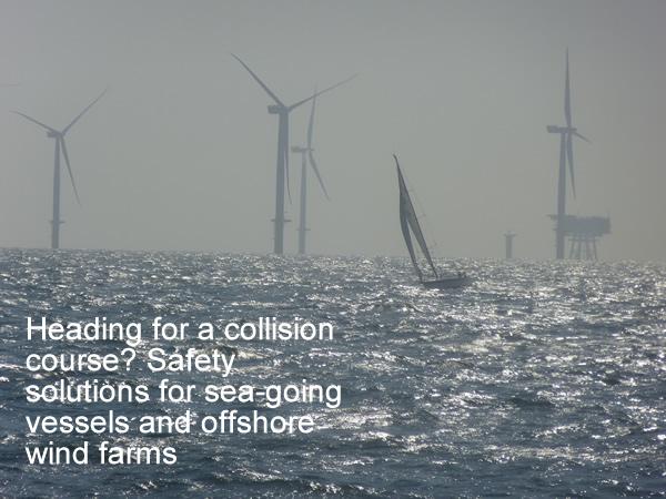
Offshore wind farms fundamentally constitute collision hazards for ships in distress or unable to manoeuvre. In-depth analysis of the dangers to people, ships and the environment is required for the scenario of a collision with an offshore wind turbine or transformer platform. Calculations of impact loads in the event of an accident are important aspects of this analysis, but cyclic operating loads from service boat landings may also affect the foundation design of the turbine.
But what are the assumptions and parameters that must be considered? What is the most suitable model to serve as a basis for calculations? And what does this mean for the design of foundation structures and offshore wind turbines? The answers to these questions are still the subject of some controversy in the offshore industry, given that empirical values, clearly formulated standards and official specifications are frequently lacking for deep-water pilot projects. In this field, characterised by dynamic innovation, the state of the art is often still in its infancy.
Project owners and managers, manufacturers, official authorities and designated approval bodies therefore face an array of technological challenges when producing collision analyses. Calculation of impacts as operating loads requires the consideration of numerous factors that substantially affect the stability and service life of an offshore wind turbine. Initial experience also shows that only extremely imprecise estimates of the loads caused by routine landing operations of small-size service boats have been carried out to date.
Collision-friendly design
Damaged vessels and deformation or failure of the components of boat landing systems at offshore wind farms significantly increase risks to crew members in the critical moments of landing and may, in some cases, result in life-threatening situations. Calculation models and analyses should therefore aim to produce turbine designs that comply with safety requirements in the case of collision, yet also safeguard functionality for reliable long-term routine operations.
At present, however, this is only possible to a limited extent under the currently established collision analysis procedure, the model scenario for which ignores landing operations. In addition to requiring the usual proof of stability, the BSH merely requires the submission of a calculation-based assessment – iterative where appropriate – of the consequences of collision, based on a reference ship that is representative of the sea area in question and on the foundation structure of the planned offshore wind turbine. Proof of collision-friendly design is deemed to be furnished where calculation models show that a single unmanned offshore wind turbine is more 'flexible' than the reference ship and would fail first in the event of a collision. In concrete terms, this means that the ship's hull (or the inner hull in the case of double-hull ships) must not give way.
How close to reality are the calculation models?
The BSH does not require collision analysis to provide precise quantified information on the extent of damage, but only give qualitative answers to the questions:
- Which would fail first – the ship or the offshore turbine?
- Which of the four categories (minor – moderate – major – catastrophic) apply to the consequences of collision?
For a qualitative analysis of these load limits and deformations in the event of collision, it may be sufficient to simplify the complex calculations by applying assumptions, provided they are based on conservative data and values. In recent years the trend in the offshore sector has clearly favoured this approach, choosing modelled ships that were more flexible (in the sense of 'softer') than they would actually be in reality and thus erring on the side of safety in terms of the collision-friendliness of the wind turbine.
However, these simplified ship models are fundamentally unsuited for the calculation and analysis of cyclic loads caused by service boats and the fatigue analyses based upon them. They may compromise the safety of the people working on wind farms, who must be able to transfer safely from the service boat to the platform. In addition, no quantitative comparison is possible when the various collision scenarios and analysis results are based on differing assumptions and calculation methods. Clearly, there is great need for coordination and discussion between all stakeholders, and harmonised standards and guidelines must be developed over the medium term.

Overview of considerations: reference ships
The initial challenge is the selection of an appropriate reference ship; the critical vessel type for the specific wind farm must be selected before any estimate of potential impact energy distribution can be calculated. The type of reference ship is selected according to the probability of collision, the environmental consequences of collision (e.g. potential volume of an oil spill in the Wadden Sea) and possible hazards for the crew and passengers of the reference ship. While it may be assumed that the wind turbine itself is unmanned at the time of collision, this is not necessarily the case with respect to transformer platforms.
To simulate the collision, a finite element (FE) model of the selected reference ship is created. In most cases this model is not based on a real ship but uses typical design features. For example, a common reference ship model is a small double-hull tanker approximately 175 metres in length with displacement of 45,000 tonnes. The engineering experts then decide on a case-by-case basis whether simplified parameters for the individual ship sections are permissible, and to what extent. For instance, the metal thickness of the hull can be virtually increased instead of undertaking detailed considerations of stiffening elements. The BSH standard does not give any information on the required accuracy of the FE model.
As a result of these largely arbitrary simplifications, the model does not correspond to reality. In addition, as assumptions are conservative it is not possible to judge the extent to which the model deviates from actual conditions. Comparison of results would be simpler if, say, the standard specified the acceptable limits of a side-impact force-deformation ratio for each separate type of ship, as normative or informative limits. This would enable the values to be used to calibrate an FE model and, where required, as the basis of analytical calculations.
Is the water mass displacement relevant?
FE approximations consider the stiffness of the ship and the wind turbine, and the mass of the ship. According to BSH, the ship floats at a rate of 2m per second perpendicularly to its longitudinal axis. Engineers also include the water mass displaced by the ship in most of their analyses, simply adding the appropriate figure. However, other analyses assume the displaced water mass to be already included in the kinetic energy of the floating ship. The BSH standard does not specify any clear details on this point.
The results of FE analyses also show that the ship comes to a standstill after a few seconds. However, the question of how the displaced water mass regains its equilibrium is still a matter of debate. Many equations are based on the assumption that the movement of the water stops when the movement of the ship stops. While this assumption can be used for a first approximation for the moment of collision, this across-the-board additive approach must be questioned in the case of secondary ship movements (i.e. reversing or turning).
The longitudinal position of the centre of gravity of a ship
If the 175-metre-long ship hits the steel construction of the wind turbine (which, in the case of monopile designs, has a diameter of five metres) at its precise centre of gravity, most of the kinetic energy at first contact will be transformed into elastic and plastic deformation – or so the majority of calculations currently assume. However, it is more likely that the point of contact is in front or behind the centre of gravity. In this case, as local deformation begins the ship will simultaneously start to rotate (mainly about its vertical and longitudinal axes). While direct contact energy and local deformations at the moment of collision are lower, the drift causes the 60 to 120-mm-thick metal sheets of the foundation structure of the offshore wind turbine to scrape alongside the outer hull of the ship, which is only 15 to 25-mm-thick; this causes dents and – in a worst-case-scenario – ruptures the hull (secondary contact).
Operating loads acting on the wind turbine during collision
Must calculations also take into account any pre-existing operational stresses caused by the wind and waves to which the wind turbine is exposed? It appears implausible that the ship can float through wind, waves and currents in the North Sea while no operational loads act on the offshore wind farm. Are these influences negligible in terms of critical strain and failure of tower stability? These issues are also ignored in the BSH standard. As no empirical values of actual collisions are available, theoretical considerations and experimental analyses must be relied on to identify possible solutions and promote a standardised analysis procedure. At present, users solve the problem by applying individual approaches; however, this produces calculations and results that are not comparable. Normative requirements have proved to be suitable structuring tools to ensure better comparability of analysis results – necessary if the findings of current pilot projects are to form the empirical basis for future projects.
Falling nacelles in the case of collision
As a fundamental principle, the stability of top-heavy designs such as offshore wind turbines is at high risk if they are hit by sudden horizontal loads at their foundation (similar to cutting down a ripe stalk of wheat). Due to the inertia of the mass focused in the nacelle at hub height (typical modern nacelles and rotors weigh between 400 and 600 tonnes), the tower segments below the nacelle are at risk of buckling. This secondary failure scenario, which may result in the nacelle and rotor falling, is not examined when planning the foundation design. As the BSH does not require separate analysis of this scenario, stakeholders usually avoid incurring the costs of commissioning additional expert reports and adjustment measures. However, in our view a detailed buckling analysis would indeed be wise given that studies by Hamburg/Harburg Technical University, which included simplified (non-conservative, linear) buckling analysis on a 350-tonne nacelle, revealed risk potential in this area.
Ground conditions on the sea bed
Previous studies have shown that the properties of the sea bed in which the wind-turbine foundation is anchored are the factor that has the highest effect on the results. A quantitative comparison of analyses is difficult or even impossible unless the analyses are based on identical soil springs.
Service boat landings
Landing operations of service boats are generally routine procedures. Mechanics and service staff land at the wind farm at weekly or monthly intervals. During landing operations the captain of the service boat must navigate the bow of the ship up to the offshore wind turbine as gently as possible, often in rough conditions with high wind speeds and waves up to 1.50 m in height. By maintaining forward thrust, the captain keeps the ship in contact with the platform, which often has only one boat landing-place consisting of a ladder and a landing station. Given this, the captain may also have to land in stern waves that press the ship against the wind turbine from behind. When waves are high and weather conditions unfavourable, "landing gently" is a relative term for the horizontal impact forces of up to
200 kilonewtons that are typically assumed in plans.
Many analyses assume that this load case does not affect the primary structure of the foundation but may only damage the bolted, welded or clamped secondary structures of the boat landing system. As long-term empirical values are wholly lacking in this field, we cannot say with certainty that the primary structure will withstand the cyclic loads caused by the service boats without long-term damage. All parties involved should therefore be aware that they are basing their plans on assumptions that may prove inapplicable in the long term under the influence of weather conditions, corrosion and complex failure mechanisms.
Accepting challenges
To determine the forces in contact with the offshore wind turbine, exact modelling of the wind turbine including soil springs and calculations carried out with a fluid dynamic programme (CFD) are required. Although this systematic analysis is very complex and cannot always be solved completely and in a satisfactory manner, previous evidence of the occurrence of damage has shown that closer examination makes good sense. The use of improved analysis models frequently provides significant value-added for owners and operators.
Given this, the regulatory requirement to prove collision-friendly foundation design need not be a cost-intensive mandatory additional measure, but may be an opportunity that significantly improves reliability and safety. It would increase the lifespan of the primary structure of the wind turbine, preventing subsequent time- and cost-intensive repairs; in addition, the secondary structures of the wind turbines and the service boats landing at the wind farm could be better aligned to each other, making them more durable and safer. This benefits plant owners and ship operators, insurance companies and the mechanics and service staff working on the steel structures, as well as the users of uninterrupted power supply.
To address these and other issues, in recent years the Hamburg-based Offshore Wind Power department of TÜV SÜD Industrie Service has continuously increased its expert staff and computer capacities to enable the simulation of maritime collision processes to be performed. Several innovative projects examine complex technological issues, including the collision of ships with offshore wind farms or the preparation of concept studies on floating wind-turbine foundations. Shipbuilders, soil mechanics, hydrodynamicists and wind-power specialists cooperate closely on these multidisciplinary issues, focusing on maximum safety and customer benefits.
The content & opinions in this article are the author’s and do not necessarily represent the views of AltEnergyMag
Comments (0)
This post does not have any comments. Be the first to leave a comment below.
Featured Product