PVWatts performs simplified PV system performance calculations using information about the arrays geographic location, orientation, and a set of user-input loss factors
Modeling Microinverters and DC Power Optimizers in PVWatts
Sara MacAlpine and Chris Deline | Solar Edge
Module-level distributed power electronics including microinverters and DC power optimizers are increasingly popular in residential and commercial PV systems. Consumers are realizing their potential to increase design flexibility, monitor system performance, and improve energy capture. It is becoming increasingly important to accurately model PV systems employing these devices, with numerous commercial [2-5] and independent research [8-11] publications providing modeling strategies and guidelines. This document summarizes existing published documents to provide uniform, impartial recommendations for how the performance of distributed power electronics can be reflected in NREL’s PVWatts calculator (http://pvwatts.nrel.gov/).
PVWatts performs simplified PV system performance calculations using information about the array’s geographic location, orientation, and a set of user-input loss factors [1]. PVWatts’ default values and recommendations for these loss factors are designed for a PV system with a central inverter, and do not account for use of microinverters or DC power optimizers. The following sections provide guidelines for choosing reasonable values to use in PVWatts to model systems with distributed power electronics.
Effects of Distributed Power Electronics in Simulation
While all of PVWatts’ loss factors can be tailored to represent individual system characteristics, a subset are particularly affected by use of distributed power electronics. Note that this document specifically addresses system losses used in PVWatts Version 5, which was updated in September 2014 and has changed slightly from previous versions of the tool [1].
Inverter: Version 5 of PVWatts allows the user to enter a nominal inverter efficiency. For microinverters, this factor should simply be the California Energy Commission (CEC) weighted efficiency; this is no different from a system with a central or string inverter. DC power optimizers’ loss term should include the combined (multiplied) efficiency of the central inverter and the optimizer devices. Efficiency in each of these cases is assumed to include the device’s effectiveness of maximum power point tracking. At present the CEC database does not include information on weighted DC power optimizer efficiency; however, this information may be provided by the manufacturer. If it is not, a value of 99% is recommended for newer devices [4,7], and a lower efficiency of 97.5% [10] is recommended for older technologies.
Mismatch: All module level power electronics are expected to eliminate mismatch losses caused by performance variation between modules. This loss factor should be 0% for all distributed electronics technologies.
Wiring: In a PV system with microinverters, DC wiring losses are effectively eliminated. However, AC wiring losses will increase since there are more and longer AC wiring routes. A recommended guideline for the wiring loss term is 2% for the entire system [6]. Wiring losses remain relatively unchanged in a system with DC power optimizers.
System Availability: Due to improved system monitoring capabilities, distributed power electronics may decrease PV system downtime, with published reports indicating that there may be potential to increase availability by a total of 1-2% [4]. While module-level conversion mitigates losses associated with point failures in a PV system, it may also result in longer time to fix these failures, as their individual impact on system performance may be too small to justify the expense of service calls. Without concrete evidence to support increased PV system availability, it is recommended that this category of losses remain unchanged, particularly if PVWatts is being used to model the first year of a PV system’s operation when equipment failures are less likely.
Shading: Both microinverters and DC optimizers have the potential to recover some of the power that is lost in partially shaded PV systems with central inverters, when obstacles block the sun’s incident beam radiation. The fraction of the losses recovered are referred to in [4] as the Shade Mitigation Factor (SMF). This value represents the annual percentage of shading losses that can be recovered through the use of distributed electronics in partially shaded PV systems. The SMF can be used to calculate an updated shade loss term by the following equation:
Shade Loss (new) = Shade Loss % * (1 - SMF)
Independent research [8,9,11] indicates that a reasonable range for distributed electronics’ SMF is 0.25-0.4, with an individual array’s SMF depending on shade distribution and extent, as well as the array configuration. The shade benefit of distributed electronics can vary with the size of the PV system, and the type of shading. A default SMF value of 0.33 is recommended here as an average value.
Soiling: Soiling is generally uniform on PV systems, so it is not anticipated that distributed power electronics would appreciably affect most arrays’ soiling losses. However, in very large arrays with regional soiling differences, or in arrays made up of modules with different orientations or tilts from one another, there may be an opportunity for some fraction of the losses to be mitigated, similar in form to the above-described Shade Mitigation Factor.
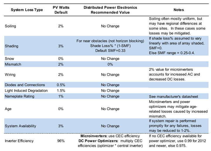
PVWatts System Losses and Inverter Efficiency
Table 1. Recommended PV Watts System Losses and Inverter Efficiency with Microinverters or Power Optimizers
References
[1] Dobos, Aron P. (2014). PVWatts Version 5 Manual. Retrieved September, 2014 from http://pvwatts.nrel.gov/downloads/pvwattsv5.pdf.
[2] Enphase Energy, Inc. (2011). PVWatts Calculation Values with an Enphase Microinverter System. (Technical Brief). Retrieved from http://enphase.com/wpuploads/enphase.com/2011/08/Enphase-Technical-Brief-PVWatts-Calculations.pdf.
[3] Bartlett, V. (2013). PVWatts Derating Factors for SolarBridge Pantheon Microinverter and ACPV Systems. (Version 1.5). Austin, TX: SolarBridge Technologies. Retrieved from http://solarbridge.wpengine.netdna-cdn.com/wp-content/uploads/2013/04/PVWatts.FIN_.pdf.
[4] Solar Edge. (n.d.). Estimating Energy in PVWatts. (Application Note). Retrieved from http://www.solaredge.com/files/pdfs/simulating_solaredge_pv_watts_app_note.pdf.
[5] Tigo Energy. (n.d.) Modeling Guide For Smart Modules. (Technical Brief). Los Gatos, CA: Author. Retrieved from http://www.tigoenergy.com/sites/default/files/modeling_smart_modules_v2.pdf.
[6] Enphase Energy, Inc. (2013). Calculating AC Line Voltage Drop for M250 Microinverters with Engage Cables. (Technical Brief). Retrieved from http://enphase.com/global/files/EnphaseTechBrief_Vdrop_M250.pdf.
[7] Tigo Energy. (2013). Datasheet Junction Box ES Series. (Datasheet). Los Gatos, CA: Author. Retrieved from http://www.tigoenergy.com/sites/default/files/mmj_es_datasheet_11.19.2013.pdf.
[8] Deline, C.; Meydbray, J.; Donovan, M. (2014). Photovoltaic Shading Testbed for ModuleLevel Power Electronics: 2014 Update, NREL Report No. TP-5J00-62471. Retrieved from http://www.nrel.gov/docs/fy14osti/62471.pdf
[9] MacAlpine, S., Erickson, R., & Brandemuehl, M. (2013). Characterization of power optimizer potential to increase energy capture in photovoltaic systems operating under nonuniform conditions. IEEE Transactions on Power Electronics, 28(6), 2936-2945.
[10] Deline, C., & MacAlpine, S. (2013, September). Use conditions and efficiency measurements of DC power optimizers for photovoltaic systems. In Energy Conversion Congress and Exposition (ECCE), 2013 IEEE (pp. 4801-4807). IEEE.
[11] Hanson, A. J.; Deline, C. A.; MacAlpine, S. M.; Stauth, J. R.; Sullivan, C. R. (2014). Partial-Shading Assessment of Photovoltaic Installations via Module-Level Monitoring. IEEE Journal of Photovoltaics. Vol. 4(6), November 2014; pp. 1618-1624.
The content & opinions in this article are the author’s and do not necessarily represent the views of AltEnergyMag
Comments (0)
This post does not have any comments. Be the first to leave a comment below.
Featured Product