In Part 1 we examined the energy bank, and the loads upon it. Next, we will explore some of the energy harvesting needs and capabilities.
A Daunting Expedition Through The Energy Harvesting Countryside.- Part 2
Thomas W. Gustin
Continued from Part 1:
SOLAR HARVESTING:
There are two basic steps, with one subsequent calculation, that we perform to determine how much power will run our system (run the loads and keep the batteries topped-off for longevity and emergency backup purposes) using just sunlight energy as a source. The assumption is that we are not receiving enough wind to help charge the system (this is often true here at the Emerald Cave).
WARNING |
|
Certain home improvement projects are inherently dangerous, and even the most benign tool can cause serious injury or death if not used properly. ALWAYS READ AND FOLLOW INSTRUCTION MANUALS AND SAFETY WARNINGS. You must be particularly careful when dealing with electricity – always use common sense. Any advice, guidance or other information provided on the altenergymag.com website or within any of our publications cannot completely anticipate your situation. If you are at all unsure about completing any aspect of this or other home wiring projects, consult a qualified electrical contractor to perform the service(s) for you. ALWAYS follow electrical code requirements specific to your area, and before undertaking any home electrical project, contact your local electrical authority and your insurance company to ensure that you comply with all policies, warranties, regulations and authorities concerning this work. |
STEP 1: Determine the total power, in watts, needed per day for the application.
This is simple since we have already discussed this topic at length. Table 3 shows how at least 2 days of emergency backup power is available, even from a battery with seriously degraded capacity (remember “people-old-age syndrome”?), for an average load of 300watts (assumes 200watts all the time with occasional short duration high power loads).
300watts x 24hours = 7.2kWatts/day.
STEP 2: Find the Insolation Level for the location of your (fixed) application.
A quick trip to the Internet reveals that the closest, yet appropriate, location to the Emerald Cave for published Insolation Levels is Columbus Ohio (about 3 days walk northeast from here). Table 5 presents these levels for the purposes of our calculations for this example:
|
Jan |
Feb |
March |
April |
May |
June |
July |
August |
Sept |
Oc |
Nov |
Dec |
AVERAGE |
|
1.64 |
2.57 |
3.26 |
4.63 |
5.4 |
6.08 |
5.73 |
5.29 |
4.74 |
3.29 |
1.97 |
1.45 |
3.83 |
Table 5: Insolation Levels for the Emerald Cave
This expresses, in kWh/m2/day, how much solar energy strikes the earth’s surface in a single day.
STEP 3: Divide the total amount of watts used per day by the Insolation Level to determine the wattage level necessary for equivalent energy harvesting capabilities.
For the average Insolation level of 3.83, we need 1,180Watts of Solar Panel energy harvesting capacity. For the minimum Insolation level of 1.45, we need 4,965Watts of Solar Panel Energy Harvesting capacity.
If this were not a hybrid energy harvesting system with integrated battery recharging capabilities, relying on solar panel power only, then the minimum Insolation level will determine the worst case solar panel requirements for this system, 4,965Watts of capacity.
Since some wind is available, coincidentally more often when the Insolation levels are at their lowest, we will use the average Insolation level for this example, that of 1,180Watts of Solar Panel capacity. Recall, too, we do have an Emergency Backup for when we “need more power” by tying to the grid a power supply for recharging our battery. Except for a component failure, our system will never over-discharge the batteries because of our Emergency Backup circuitry.
200+WATTS SOLAR PANELS:
To achieve a minimum of 1,180Watts of harvested solar energy per day, using the average Insolation Level of 3.83, requires six solar panels (as shown in Figure 3) providing 200Watts or more, average. Fortunately, many 24volts-rated solar panels have this power rating available on the market.
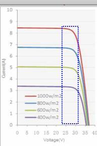
Figure 3 also shows that the solar panels connect to the batteries through commercial “charge controllers.” It is important to note at this time that these electronic components impose power losses by their insertion. Many of these controllers typically run ~85% efficiency. To “make up” for these circuit losses, our system should strive to use 235Watts (or slightly higher) Solar Panels, if possible.
Figure 5 depicts the Current versus Voltage curves, for four different sunlight intensity levels, for a typical 235Watts, 24volts-rated solar panel. The blue dashed rectangle highlights the general region of power contribution to our system. The left vertical line, at ~23volts, emphasizes the operating point when the batteries drain down to ~50% DOD (see Table 4), while the right vertical line accentuates the operating point when the batteries “top off” (full) and the charge controllers are on the verge of disconnecting their respective solar panels from the batteries. As a reminder, 1,000 watts per square meter occurs in bright, overhead sunlight.
Figure 5: 235Watts Solar Panel Power Curves
The amount of power delivered from the solar panel is, therefore, highly dependent upon both the amount of light striking it and the battery voltage (SOC), as shown by Table 6.
|
Light Intensity |
Battery @ ~23volts |
Battery @ ~32volts |
||
|
Solar Panel Current |
Resultant Power |
Solar Panel Current |
Resultant Power |
|
|
1000w/m2 |
~8.4amps |
~193watts |
~7.0 amps |
~224watts |
|
800w/m2 |
~6.8 amps |
~156watts |
~5.8 amps |
~185watts |
|
600w/m2 |
~5.0 amps |
~115watts |
~4.5 amps |
~144watts |
|
400w/m2 |
~3.2 amps |
~73watts |
~3.0 amps |
~96watts |
Table 6: Power from a 235Watts Solar Panel as a function of light and battery voltage
µWIND POWER:
There are many wind map resources available on the Internet. Picking one, the National Renewable Energy Laboratory (NREL, at www.windpoweringamerica.gov), shows that the Emerald Cave has an annual average wind speed of 6.5m/s (=14.54mph), 80 meters (= 263 feet) up (how handy is that!). Information on that same web site also states that the “NREL filtered the wind potential estimates to exclude areas unlikely to be developed, such as wilderness areas, parks ...” which, of course, accurately describes The Emerald Cave. Ok, well there is no intention of developing a wind farm consisting of 260 feet tall wind towers poking through the tree canopy. I wish to harvest what I can get much closer to the ground when possible since it is a supplemental energy scavenging resource.
There are many different kinds of micro wind turbine power generators available on the market, perhaps too many to make an easy choice possible. Some of my Engineering Research and Development work for various clients have involved studies into alternative methods of harvesting wind; but no examination of these special cases (special applications requiring unusual methods) will occur in this little paper.
There are two primary electrical interfaces to most micro wind-turbine power-generators. Many of them provide the raw electrical interface created by the internal rotating magnetics, brushless permanent magnet alternators (PMA’s), via three wires to the three-phase alternating current (3ØAC) windings. Some wind turbines contain within them (usually very high-loss, low-efficiency) three-leg full-wave rectifiers that convert this native 3ØAC to direct current (DC), whose voltage levels (in both configurations) increase proportionally with the increase in revolutions per second.
HORIZONTAL or VERTICAL:
There are two primary categories, with many variations, of micro wind turbines, generally listed as horizontal or vertical axis (of rotation). The most prolific micro wind turbine (as shown in Figure 3) in use is the triple-propeller horizontal turbine (look like miniature versions of the very large machines used in commercial-grade wind farms). The most common vertical axis wind turbines (VAWT) are the Savonius (“S” shaped when viewed from the top) and Darrieus (looks like a giant eggbeater).
MARINE-GRADE HORIZONTAL:
Horizontal Axis Wind Turbines (HAWT), usually with its characteristic tail that keeps the turbine facing into the wind, often have some hidden (except from experience) operational issues not always apparent (as its tail). If one is going to invest in a wind turbine that will easily run for at least 20 years problem-free, then paying for one that circumvents longevity issues is wise. For instance, obtaining a HAWT that tolerates salty, very-high-speed gusty-wind environments common to marine applications is a good avenue to follow. Even though there is no salt-spray at the Emerald Cave, I do not want to have to climb a tall extension ladder every few years to clean natural (dirt) “buildup” and/or repair weather-related operational issues (like a bent tail from a falling stick, frozen rotor from a hail and ice storm, etc.). Getting a Marine-grade HAWT with a weatherproof finish is worth the costs, up front. The best way to deal with a bent-tail issue is not to have one in the first place.
Another, not obvious until it is a big problem, issue is how the power from the PMA connects to the rest of the system. Remember that a HAWT points into the wind, with the ability to swing in all directions. If the power cable from the PMA is a hard-connected cable, then it will only twist around a few times before it impedes further rotation, requiring another trip up that long extension ladder to rotate the whole assembly backwards a few rotations to permit free movement with wind direction. The best solution to this potentially irritating problem is to obtain a HAWT that uses yaw-slip rings to couple the PMA generated energy to the cable (inside the mast) to the rest of the system. Did I mention that I do not much like climbing really tall extension ladders anymore?
.jpg)
Leading Edge Turbines (www.leturbines.com) is an example of a Marine-Grade high performance unconventional triple-blade HAWT. There is no tail to perform yaw steering; the ‘X-wing’ chassis does that. The fully- integrated yaw-slip- rings in the sealed- body permits 360 degrees of continuous yaw rotation, without the output cables becoming twisted or tangled.
The rotor diameter is 1 meter (= 3.28 feet). The Blades are UV resistant and extremely tough Glass Reinforced Nylon for dealing with severe weather conditions. UK designed and built, the LE-300 Turbine is a pricey £479.00.
The LE-300 has a cut-in wind speed of 3m/s (=6.7mph), which means it will work here at the Emerald Cave. In fact, Figure 7 shows how the LE-300 will contribute ~50watts of power, on average, provided it is 263 feet up in the air.
Figure 6: Leading Edge Turbines' LE-300 HAWT
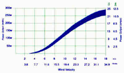
Figure 7: LE-300 Performance Curve
Figure 7 shows that the LE-300 will provide: ~50Watts @ 15.7mph, ~100Watts @ 20.1mph, ~150Watts @ 24.6mph, ~200Watts @ 29.0mph, ~250Watts @ 35.8mph, and ~275Watts @ 40.2mph (had more than that in wind gusts yesterday here at the Emerald Cave).
Readers that do not have issues with climbing tall ladders in blinding snowstorms may want to consider a HAWT that is less expensive…
6-BLADE HAWT:
The GudCraft WG300 (www.gudcraftonline.com) is an interesting variation on the archetypal propeller HAWT because it has six blades instead of three (yes, it also has a tail).
With a list price of $700.00, this unit is on sale for $299.00 at the time of this writing.
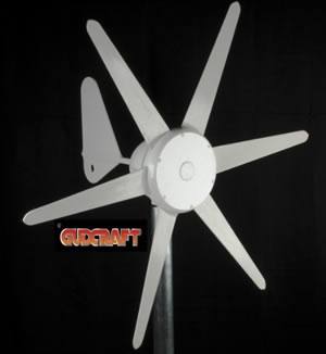
Figure 8: GudCraft's WG300 6-blade HAWT
VERTICAL AXIS WIND TURBINE:
While rated at a lower capacity (of 200Watts at 29mph), this small VAWT is a durable power source that naturally circumvents many difficulties common to HAWT resources. The aeronautics-based wings are just 3.3feet tall with a rotating diameter of just 3.4feet. Its start-up speed is a low 2.9mph, contributing power at ~5.6mph, with a survival wind speed of 134mph.
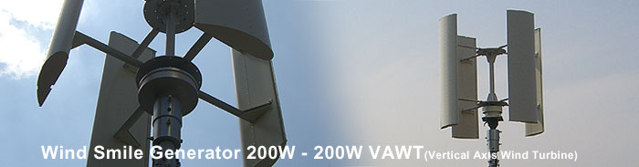
Figure 9: Wind Smile's 200W VAWT
This VAWT is quiet (no blade swishing sound), and it begins rotating with a gentle breeze, able to absorb wind energy from any direction, with no cable twisting issues.
…like a drink of water from a fire hose…
My publisher thinks that I should save the rest of these discussions for part 3 of this little expose’ into the wild land of hybrid energy harvesting systems. Next time we will examine some of the features and functions of various types of commercial “controllers,” including their (in) ability to report the state of the system in an integrated manner. That discussion will include some technical areas regarding “specmanship” to watch out for while researching system components. We will look at feasible configurations for controlling multiple loads, using various easily obtainable components. We will also try to deal with the problem of the “user supplied resistive load” portion of the system that protects the battery from wind turbine caused over-charging events.
While I am not presenting a “Heathkit” approach to building a hybrid energy harvesting system, I am trying to make the technology to build a system more understandable and accessible to the “do-it-yourself” readers who are inclined to try out some of these ideas.
One last major topic that remains is what to do about using eleven different commercial controllers in our example system. After our (future) thoughts about commercial controllers, we will investigate an alternative approach using a simple, integrated, passive (quieter, no EMI), less expensive, smaller, and more robust controller concept that includes a system-wide Health Monitoring System for reporting system status.
Until next time, take a little breather…
The content & opinions in this article are the author’s and do not necessarily represent the views of AltEnergyMag
Comments (0)
This post does not have any comments. Be the first to leave a comment below.
Featured Product