How to Obtain the Extra Energy Gain Promised by Bifacial Technology
By Javier Tamayo, Design Engineer, STI Norland
Over the last few years, there has been an increasing trend in the use of bifacial solar panels, a technology already assessed a few decades ago, but which due to its high cost failed to expand. It has been recently that optimized manufacturing processes have allowed bifacial panels to compete with monofacial panels.
The solar generation gain in the change from monofacial to bifacial is currently around 6-8%, a percentage known as bifacial gain, which is conditioned by multiple factors.
More specifically, there are three base parameters directly determining photovoltaic project bifaciality, namely the following (in order of relevance):
Amount of irradiance: Obviously, the more light received, the more electricity can be generated from solar resources. It is important to mention that most captured irradiance comes in the form of direct irradiance, which is reflected on terrain areas not affected by the solar panel own-shading on the ground.
Albedo: It refers to the proportion of irradiance actually reflected by the ground. It depends on the type of terrain used in each project and varies throughout the year. As a reference, common sandy terrain has an average albedo value of 0.25.
View factor: It is directly linked to the geometry and position of the irradiance capturing surface (panels), in relation to the irradiance-emitting surface (ground). Thus, analyzing the tracker choice is paramount to ensure bifaciality adequacy. In other words, it is essential to thoroughly assess the amplitude with which tracker panels capture ground-reflected irradiance.
As abovementioned, out of these three key factors, the first two are specifically defined for each project:
-
Irradiance is determined by geographical location.
-
As for albedo and despite the availability of techniques to improve this parameter, it is not so clear to date to which extent investing and optimizing albedo will establish itself as a common application of bifacial projects. However, the geometric form factor does vary within a project for the same irradiance and albedo, depending on the solar tracker used.
Analytical approach to bifaciality
Normalized height – aspect ratio
According to an analytical approach, irradiance reflected and captured by a collector is not related to collector size.
As long as the collector is installed at a distance proportional to the surface that reflects solar irradiance, it should in return reflect the same irradiance.
The width of the emitting surface grows proportionally to the increase in the collector height, so it should capture the same irradiance in return.
That is known as normalized solar tracker height. In the solar industry the concept 'aspect ratio' is also used, a parameter that comes from the aerospace engineering.
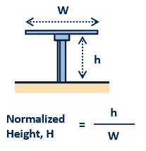
Figure 1. Normalized height concept
In larger collectors, an increasing number of photovoltaic cells is installed at a larger height. The irradiance-reflecting ground width is also larger, meaning the percentage of rear irradiance capture is eventually the same, regardless of solar tracker size.
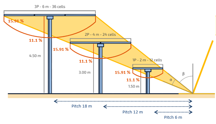
Figure 2. Equivalent trackers of normalized height value
However, due to aspects not relating to bifaciality, such as adequate solar installation height, the 2P array available in the marketplace located at a lower normalized height step compared to the 1P array.
That means the obliquity of solar rays impacting on the 2P collector increases, and it implies a less intense reflected irradiance captured by the cells.
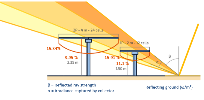
Figure 3. Different geometrical condition on solar trackers
The more or less efficiency on this geometrical tracker condition is directly linked to the view factor (VF) of it.
Apart from the VF itself, there are two basic parameters that imply a later adjustment in the captured irradiance:
-
Mismatch. The fact that reflected rays impact on the photovoltaic cells at different angles, results in captured irradiance differences. This difference or mismatch translates into reduced power generation by the panel as a whole. For common solar tracker geometry and albedo values, the mismatch ranges between 1% and 3%.
-
Shading factor. The shades produced by the own structure of the solar tracker also imply a reduction in power generation. In this regard, the torque tube and the purlins are the intermediate elements responsible for most of the backside shading. In the existing marketplace, and considering the most common solar tracker configurations, 1P and 2P, we are referring respectively to torque tube of square elements with a width of 100 mm or 150 mm installed, at a mere 200 mm from the capturing surface, which is the photovoltaic panel row.
Regardless of the projected tracker, shading affects mostly the central photovoltaic cells, which sit closer to the torque tube. For common tracker geometry and albedo values, the shading factor ranges between 3% and 6%.
Not only the torque tube but the purlin itself is also located along the trajectory of the ground-reflected rays coming diagonally towards the PV panel. The larger the purlin is, the more interference will produce. In this sense, a typical 1P purlin of 440 mm produces lower affection in terms of shadowing than the common 2P purlin of 2350 mm. This length requirement or restriction comes directly from the fixing options of the modules, where fixing in both halves of each module is needed.
Purlin profile height
Getting into detail in the magnitude of the torque tube shading, we see that the height of the purlin may vary its value. The purlin is the tracker part that connects the photovoltaic modules to the torque tube and creates a space between them.
An in-depth analysis of the purlin height reveals that an increase of 10 mm implies a reduction on the shading factor value of around just only 0.1%.
On the other hand, higher purlin profiles mean a greater non-balance on the tracker, as the modules mass is located further from the rotation axis.
This requires a higher structural demand on the torque tube and the motor resistances.
Torque tube-induced shading practically vanishes in the absorbing surface in a similar order of magnitude, regardless of the distance to the capturing surface, always considering a realistic purlin height of 40-80 mm.
The torque tube shade can be assessed as a sum of the different shades coming from different rays, each of them with different solar irradiance intensity (the largest coming obviously from the sunlight area of the ground):
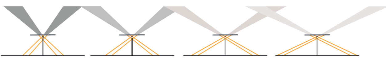
Figure 4. Torque tube shade differential calculus
In order to avoid the major part of the torque tube shade, and to produce a substantial aid, the purling should be around 15,350 mm height, an ideal concept that cannot be implemented in real projects.
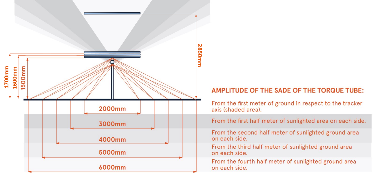
Figure 5. Torque tube shade intensity
As for shading distribution, it is observed that as the separation between the shade-generating element and shade-absorbing element increases, shading dissipates more uniformly on the intermediate or central cells, spreading progressively to the adjacent ones.
Lower height of the purlin produces a higher concentrated peak on captured irradiance between the different cells of the module.
This difference eventually causes an electrical mismatch that produces a reduction in solar production. As a first approach in mismatch magnitude, we see a natural value because of the edge effect of around 1.4 % (blue line in the graph below) for common albedo values. Adding the torque tube as the shade-creating element, that value is increased to around 2-3 % (orange line).
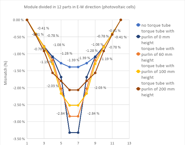
Figure 6. Electrical mismatch vs purlin height
The existing design of STI Norland includes a purlin at a height of 60 mm, thus allowing common bifacial panels with a 30-mm frame to have a free space of 90 mm between the torque tube and the rear side of the panel. The mismatch value here is about 2.8 %.
As seen in the distribution, the reduction affects not only the intermediate cells 6 and 7 but also to the adjacent ones 4, 5, 8, and 9. This means that the torque tube shade is spread throughout a large part of the rear side of the module.
Leaving a gap in between the two modules in the 2P configuration does not avoid that shade. Besides, it implies lowering the view factor of the tracker as the PV surface increases in width but not in height.
The shade of the torque tube impacts on the rear side of the module, no matter the gap in between the modules:
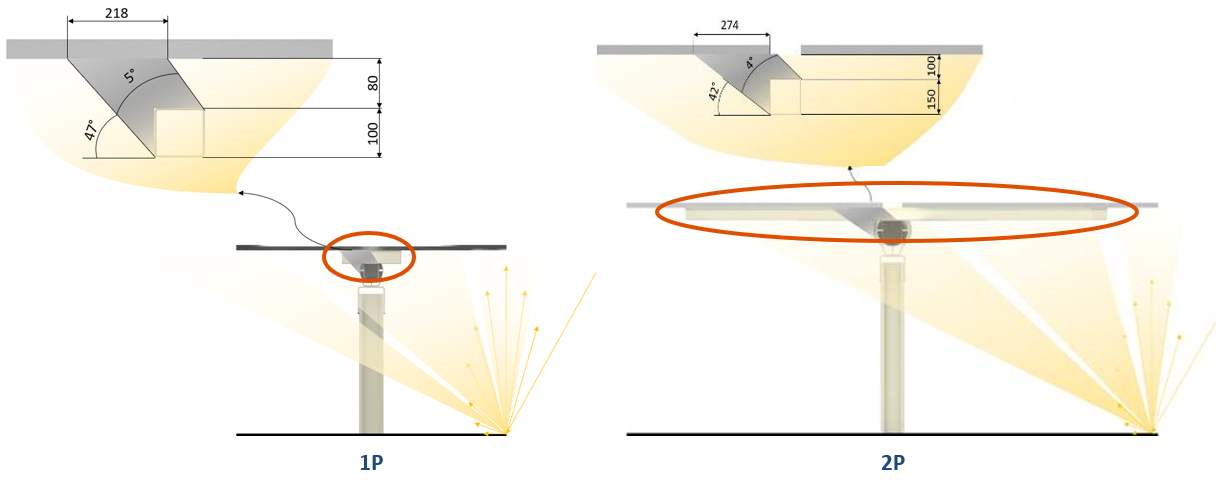
Figure 7: Torque tube spread shade in the rear side of the module
Bifaciality analysis conclusions
Considering the abovementioned bifacial parameters, it is possible to assess how bifacial gain increases in relation to normalized solar tracker height, or its aspect ratio, as it is also known in the market.
For a common albedo of 0.25, bifacial gain can be expected to increase a few tenths of percentages when normalized height increases 0.05. In other words, the height of our 1P tracker should be raised 100 mm for a 2-meter collector.
The two bifaciality steps for the two most common configurations in the marketplace (1P and 2P) are presented below for a specific position of 0º (which generates the largest rear irradiance in absolute terms of W/m2):
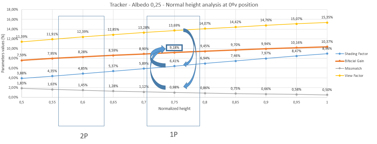
As illustrated, bifaciality is more beneficial for increased normalized solar tracker module height. This suggests, if costing allows it, that trackers can be installed higher from the ground if monofacial panels with larger supports are used.
To define optimal height, it is necessary to consider other technical factors which make the analysis more complicated, such as the type of soil and wind load, in addition to the inherent difficulty of installing trackers at an increased height.
In any case, bifacial panels have become increasingly popular over the last few years. Now it is a matter of understanding how this promising technology, which has clear and solid advantages, evolves in the future.